Introduction
My friend of Ham radio operator said receiving desired weak signal readability ranking are
DS_SDR > TS-590 > FTdx5000 at 20m band and low band (80m and 40m), and other ham said receiving desired weak signal readability ranking are TS-590 > FTdx5000 at low band (80m and 40m), however FTdx5000 can’t detect and read to the same desired readable weak signal.
Those are DS_SDR heard 100% desired readable weak signal, TS-590 detects but heard not complete reading about the same desired readable weak signal and FTdx5000 heard nothing about the same desired readable weak signal. (DS_SDR : direct sampling SDR, SunSDR2 PRO/MB1)
Then I check ARRL’s MDS(minimum discernible (or detectable) signal) and result are -131dBm <-130dBm <-126dBm, thus almost very close values and contradict the fact of above readability ranking.
Those differences have to more than 10dB between DS_SDR and TS-590, more than 6dB between TS-590 and FTdx5000. And then I checked MRSL are -121dBm < -107dBm < -98dBm, thus those MRSL values validity of readability ranking and phase noise relations.
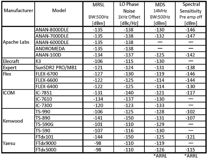
Table 1. MRSL , LO(Local Oscillator) Phase Noise, MDS & Spectral Sensitivity
Another information are TS-890’s weak signal readability better than TS-590, TS-990 and other rigs, thus many DX use with TS-890.
Then I check MDS and MRSL for above rigs which are -131dBm<-130dBm<-128dBm and -141dBm <-107dBm <-106dBm, those MDS values have very close and contradicted, thus those MRSL values have application.
And another information are FTdx101’s weak signal readability better than FTdx5000 and FTdx9000, thus many DX use with FTdx101.
Then I check MDS and MRSL for above rigs which are -125dBm<-119dBm>-126dBm and -144dBm <-98dBm =-98dBm, those MDS values have dispersion and contradicted, thus those MRSL values have application.
I check table1 for relation between MRSL, LO(Local Oscillator) Phase Noise and MDS, thus those MDS values have many contradict values such as FTdx9000 versus FTdx5000, TS-890 versus FTdx101, IC-7851, ANAN-100D versus SunSDR2 PRO/MB1, also ANAN-7000DLE versus ANAN-100D.
Unfortunately MDS can’t related to clock oscillator (CO) phase noise and LO phase noise (offset under 10kHz) which refer to References 2. MDS requires absolutely related to CO and LO phase noise, unfortunately MDS can’t related those phase noise and can’t discus about those phase noise.
As above problems then I am thinking about MRSL cause LO and CO phase noise (offset under 10kHz) also under the condition of typical DX pileup situation and typical low band situation.
Back ground
In 2014, “First CD cutting in the world using cesium beam frequency standard ” which using my own cesium beam frequency standard for audio clock synchronizing standard(PAT).
This CD cutting (24bit to 16bit) result have noise floor level is under -130dB and THD is under -100dB which performance have absolutely silent, real pure sound quality and excellent sound localization.
This cesium beam frequency standard(Cs-STD) is FTS4050 (LTC:16s) and includes FTS1000 OCXO which have sufficient low phase noise and sufficient high frequency stability, refer to table 2 and 3. And also I didn’t use my own HP5061A/B which depends on insufficient low phase noise.
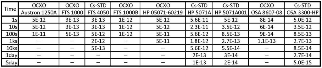
Table 2. Frequency Stability: Specific OCXO and Cs-STD
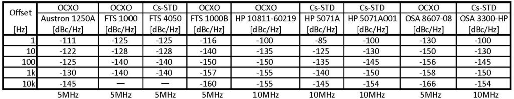
Table 3. Phase Noise: Specific OCXO and Cs-STD
I own HP5061A/B, HP5071A001, FTS4050, FTS4060, FTS4065B, BVA:OSA 8607-08, FTS1000B,FTS1050A , Austron 1250A, Austron 2010B , RMS 1320 (VLF/LF Phase Tracking Receiver), TRACOR 599K (VLF/LF Phase Tracking Receiver), GPS equipments (includes GPSDO) and rerated other equipments.
In 2017, my friend of Ham radio operator said above receiving desired weak signal readability ranking for from ARRL’s measuring MDS values and others then I checked LO and CO phase noise for those values, unfortunately nothing about LO and CO phase noise for MDS, RMDR and others.
About this problem then I betted LO and CO phase noise (offset under 10kHz) performance have to discus for HF receivers and transceivers. And I betted references 8 Emmanuel Ngompe described reciprocal mixing effects to published in APPLIED MICROWAVE & WIRELESS Jan.1999 pages between 54 page and 58 page “Computing the LO Phase Noise Requirements in a GSM Receiver” for this MRSL performance.
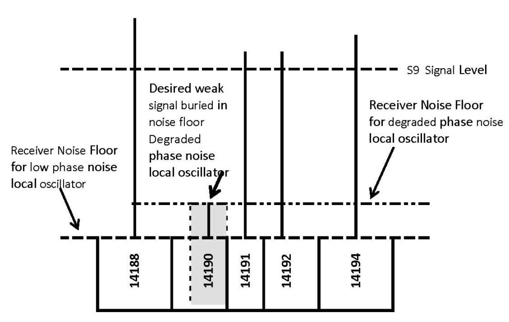
Fig 1. Typical DX pile up situation in the frequency(kHz) domain
1. Primary key receiver performance under the condition of typical DX pileup situation and typical low
band situation
Primary key receivers performance under the condition of typical DX pileup situation and typical low
band situation concerning LO phase noise or CO phase noise (offset under 10kHz) and reciprocal mixing effects.
1-1. Reciprocal mixing effects under the condition of typical DX pileup situation
LO phase noise or CO phase noise (offset under 10kHz) and reciprocal mixing effects under the condition of typical DX
pileup situation which refer to Fig.1 and this condition exclude nearby signals excessive phase noise.
1-1-1. Nowadays, typical DX pileup situation is much more crowded under 2kHz narrow separation and
station to station, thus increases the noise floor for phase noise in LO or CO according to reciprocal
mixing effects. Therefore desired weak signal buried in increased noise floor.
1-1-2. Phase noise level for LO and CO requires under -135dBc/Hz 1kHz offset from carrier and under 145dBc/Hz 10kHz offset from carrier furthermore the S1 signal level is -121dBm which refer to chapter 1-6-3.
1-1-3. Above conditions precedent is more than 100dB of 2kHz spacing two tone third order IMD dynamic range (TT_TO_IMD_DR).
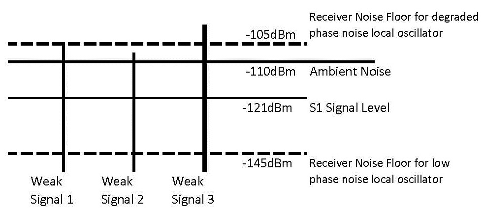
Fig. 2 Typical Low Band Ambient Noise and Weak Signals.
1-2. Reciprocal mixing effects under the typical low band situation and ambient noise
LO phase noise or CO phase noise , reciprocal mixing effects and ambient noise under the typical
low band situation which refer to Fig.2.
1-2-1. Typical low band situation is much more ambient noise, thus increases the noise floor for phase
noise in LO or CO according to reciprocal mixing effects. Therefore desired weak signal buried in
increased noise floor.
1-2-2. Fig.2 shows desired weak signal 1 and 2 buried in assumed receiver noise floor for degraded phase
noise local oscillator and ambient noise.
1-2-3. Assumed ambient noise level nearly equal to 1kHz offset reciprocal mixing then noise floor
adding about +6dB from ambient noise level.
1-2-4. Those assumed Noise floor depends on 1kHz offset phase noise in LO or CO, however under
investigation for ambient noise relation of 100Hz offset and 1kHz offset phase noise in LO or CO.
1-3. Reciprocal mixing
1-3-1. Condition of typical DX pileup situation’s equivalently strong clean interferer signal increases noise
level in IF bandwidth for phase noise in LO or CO according to reciprocal mixing effects, thus desired
weak signal buried in this noise.

Fig. 3 Reciprocal Mixing Process
1-3-2. Reciprocal mixing process (refer to Fig.3)
1-3-3. Requires important matters for reciprocal mixing that details of desired weak signal level under
the condition of typical DX pileup situation and equivalently strong clean (Ultra Low Phase Noise
Level) interferer signal and signal level and also LO phase noise level on receiving frequency or CO
phase noise level on clock frequency.
1-4. Reciprocal mixing and equivalently interferer signal, desired weak signal
Reciprocal mixing under the condition of equivalently strong clean (Ultra Low Phase Noise Level)
interferer signal and desired weak signal as follows:
1-4-1. Equivalently strong clean interferer signal’s level of phase noise requires under -140dBc/Hz 100Hz
offset from carrier, under -150dBc/Hz 1kHz offset from carrier and -160dBc/Hz 10kHz offset from
carrier at 14MHz, thus existing rigs (refer to table 1 and 7) example as phase noise level is less than
-135dBc/Hz 1kHz offset from carrier and -145dBc/Hz 10kHz offset from carrier at 14MHz.
1-4-2. Recommend equivalently strong clean interferer signal level is 0dBm (S9+73dB). If saturation or
clip occurs then this level goes down to -5dBm (S9+68dB), -10dBm (S9+63dB), -15dBm(S9+58dB) or
-20dBm (S9+53dB) which requires 1kHz offset from desired weak signal.
1-4-3. Desired weak signal and signal level ingenerate general purpose SG or additional above ultra low
phase noise analogue type SG.
This SG requires phase lock to above ultra low phase noise analogue type SG’s external reference
output 10MHz.
1-4-4. Synchronize to distributed external 10MHz frequency standard requirement which
refer to refer to chapter 1-9.
1-5. MRSL (minimum readable signal level) and receiver configuration
1-5-1. Receiver’s sensitivity degraded by reciprocal mixing with LO or CO phase noise and receiver
configuration as follows:
a) Direct Sampling SDR
b) Direct Conversion
c) Single Conversion (One mixer)
d) Double Conversion (Two mixers)
e) Triple Conversion (Three mixers)
Assumed factor is RF mixing stage and degraded 3dB each mixer.
1-6. Assumed approximation equation for LO phase noise and MRSL
1-6-1. Reciprocal mixing effects for the required LO phase noise and equation
Emmanuel Ngompe described reciprocal mixing effects (references 8) for the required LO phase
noise and may be estimated using the following equation:
L(Dfc) [dBc/Hz] = Sdes-Sbl(Dfc)-C/Ireq-10log(BW)
L(Dfc) = phase noise in dBc/Hz at Dfcoffset
Sbl(Dfc) = magnitude of the blocker (interferer signal) in dBm (or dBV)
C/Ireq= minimum magnitude of the required carrier-to-interference ratio at the baseband
processor input in dB
Sdes = desired signal level in dBm (or dBV)
BW= receiver noise bandwidth
1-6-2. Required LO phase noise equation transformed to estimated and desired weak signal level as
follows: Sdes [dBm] = L(Dfc)+Sbl(Dfc) + C/Ireq + 10log(BW)
1-6-3. Reciprocal mixing effects for the desired weak signal level (MRSL) equation
Reciprocal mixing effects for the desired weak signal level in dBm may be estimated using the
following assumed and modified for HF receivers and transceivers equation.
MRSL [dBm]= (1kHz offset phase noise in LO or CO) +0 +6+10log BW +MN
= (1kHz offset phase noise in LO or CO) +MN+3
Interferer signal level: 0dBm
SNR: 6dB
BW: kHz (Basic condition: 0.5kHz)
Mode: CW
MN: Mixer Noise which depends on receiver configuration [dB]
Direct Sampling SDR : 0
Direct conversion :0
Single conversion : 3
Double conversion : 6
Triple conversion : 9
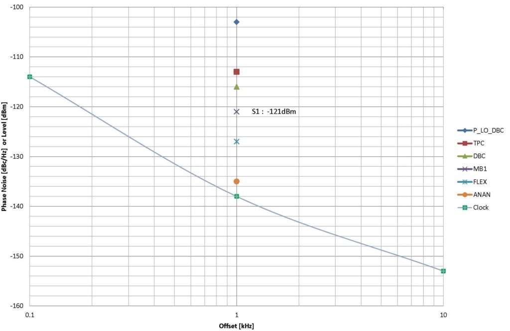
Graph 1. MRSL, S1 Signal Level & Clock Phase Noise
1-7. Graph 1 for compare CO phase noise and MRSL
1-7-1. Graph 1 for compare CO phase noise data CVHD-950 VCXO and calculated MRSL values
which according to above equation, refer to Table 1.
1-7-2. MRSL values according to Table 1 and ranking as followings:
ANAN < FLEX < DS_SDR < DBC <P_LO_ DBC < TPC
ANAN: Apache Labs Direct Sampling SDR
FLEX: FlexRadio Systems Direct Sampling SDR
DS_SDR: Expart SunSDR2 PRO/MB1 Direct Sampling SDR
DBC: Typical Double Conversion
P_LO_DBC: Double Conversion with poor phase noise LO
TPC: Typical Triple Conversion
Assumed MRSL values depends on above equation and each phase noise data comes from DDS
application notes, catalogs, makers answer and others.
*Expect FTdx101 and TS-890 depend on transmit IMD problem and refer to Table.6.
1-8. Comparison Table for HF receivers and transceivers
Comparison Table for HF receivers and transceivers includes calculated MRS values according to
above equation and other data comes from QST review and others, refer to Table 1 and Table6.
(Refer to Table 3, 4 and 5)
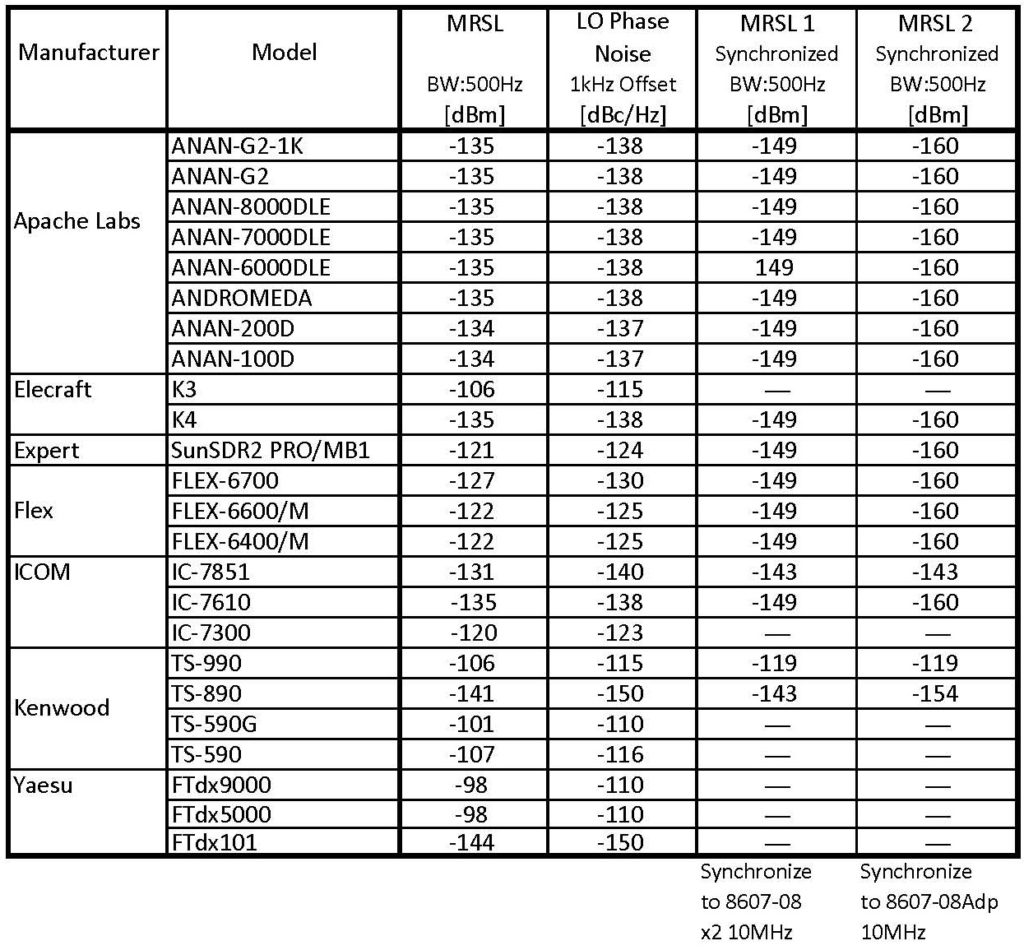
Table 4. MRSL for Synchronized Low Phase Noise Disciplined OCXO
1-9. Prohibited matter under mentioned:
(1) Some SDR includes optional GPSDO in spite of degrading CO phase noise, therefore don’t use
optional GPSDO, thus only stability and accuracy for frequency.
(2) Don’t use general kind of GPSDO due to degrading phase noise.
(Exception is described in the item 1-9-2.)
(3) Don’t use general kind of Rubidium oscillator due to degrading phase noise.
(Without exception)
(4) Don’t use general kind of Cesium beam frequency standard according to degrading phase noise.
(Exception is described in the item 1-9-3.)
1-9-1. Following items for selection of GPSDO and conditions.
(1) Improved GPSDO includes VC_OCXO (Examples: FTS 1000B, OSA 8607-08,SRS SC10A, Rakon
ROX525T1 10MHz, Wenzel 501-27517-01, 501-27501-01) and PLL have more than 50 seconds
LTC (loop time constant), thus don’t occur degrading phase noise.
(2) General kind of GPSDO and connect through Microsemi (Symmetricom) ultra clean phased lock
oscillator (disciplined OCXO) 4145B or 4145C and to change the time constant (LTC) :50.0s, thus
don’t occur degrading phase noise (Factory default value is 5.0 seconds.) therefore 10MHz output
have low phase noise, however input frequency 5MHz only and requires frequency doubler for
GPSDO output 10MHz.
(3) GPS/GNSS disciplined paticular 10 MHz OCXO and paticular Rubidium oscillator
(a) Quartzlock: E8000/3 or E8000/2
(b) Microsemi: GPS-3500ULN or GPS-3300 LN
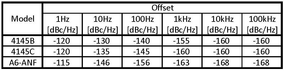
Table 5. Low Phase Noise Disciplined OCXO
1-9-2. Cesium beam frequency standard
(1) 5071A, 5071A/001 (HP, Agilent, Symmetricom now Microsemi)
Those are typical laboratory use cesium beam frequency standard, however those phase noise
under -140dBc/Hz at 1kHz offset, thus connect through above 4145B /4145C or Quartzlock A6-ANF
or other disciplined low phase noise OCXO.
(2) Microsemi (Datum, Symmetricom) Cs4000 or CsIII 4310B and to change the Loop Tau (LTC) :50.0s,
thus don’t occur degrading phase noise.(Factory default LTC value is 1.0 seconds.)
(3) FTS, Datum (Symmetricom) 4065A/B/C and to change the time constant (LTC) :50.0s, thus don’t
occur degrading phase noise. (Factory default LTC value is 5.0 seconds.)
2. Conclusion
Primary key receiver performance under the condition of typical DX pileup situation and the typical
low band situation concerning local oscillator (LO) phase noise or clock oscillator (CO) phase noise and
reciprocal mixing effects which results are MRSL (minimum readable signal level).
We requires reciprocal mixing test or calculating for MRSL.

Table 6. HF Transceiver Comparisons for MRSL, LO Phase Noise and others
References
1. Bob Allison, WB1GCM described “Reciprocal Mixing Testing: What is” to published in QST April 2013
page 55.
2. ARRL described item 5.7A reciprocal mixing in chapter V. receiver test to published in ARRL
Laboratory’s “Test Procedures Manual ” Revision N. Dec. 31 2014 pages between 50 page and 52
page.
3. Tadeusz Raczek SP7HT described LO phase noise and reciprocal mixing under the condition of typical
DX pileup situation to published in QEX Sep/Oct 2002 page 39.
4. John Eisenberg K6YP described Reciprocal Mixing to published in PPT “What makes a receiver grate? “
pages between 18 page and 20 page.
5. James R. Fisk W1DTY described MUS (minimum usable sensitivity) to published in a Ham Radio
Magazine Oct 1975.
6. Nigel Clement Davies described reciprocal mixing to published in Digital Radio and Its Application in
the HF (2-30 MHz) Band, May 2004, page 87 for 5.3 HF Receiver Performance Requirements and page
93 for reciprocal mixing.
7. Tired, Tobias described reciprocal mixing to published in High Performance LNAs and Mixers for Direct
Conversion Receivers in BiCMOS and CMOS Technologies. 2012-03-04 page 24.
8. Emmanuel Ngompe described reciprocal mixing effects to published in APPLIED MICROWAVE &
WIRELESS Jan.1999 pages between 54 page and 58 page “Computing the LO Phase Noise
Requirements in a GSM Receiver”.
9. Ali M. Niknejad described Mixer Noise to published EECS242 pages between 2page and 7page ” Mixer
Noise and Design”
・
If you have a question please E-mail to ja2gxu@cpost.plala.or.jp (@ → @)